研究成果藝廊 > 格陵蘭望遠鏡與次毫米波特長基線干涉儀計畫(GLT)
研究成果藝廊
格陵蘭望遠鏡與次毫米波特長基線干涉儀計畫(GLT)
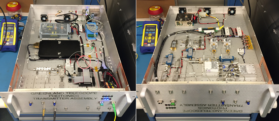
| Photonics Local Oscillator Transmitter, GLT Project |
|
圖片來源: Derek Kubo

Internal photos of Photonics LO Transmitter instrument. Left - top view of optical and RF components including Optilab 40 GHz transmitter, erbium doped fiber amplifier, 30 GHz receiver, low noise DC power supply, and ADAM monitor & control. Right - bottom view of phase lock sources, RF components, DC power supply for cooling fans, and voltage regulation.
|
| This instrument accepts 10 MHz and 100 MHz from the hydrogen maser along with a tunable low phase noise LO ranging from 18 to 31.5 GHz. A pair of internal PLS' locked to 10 MHz generate 15.75 and 15.76 GHz reference tones. The 100 MHz, 15.75 GHz and 18 to 31.5 GHz signals are summed together and transmitted to the GLT antenna over a single fiber at 1557.2 nm. The 3 signals are separated in the corresponding Photonics LO Receiver unit within the antenna where 100 MHz is used to generate a 10 MHz antenna reference, and the 18 to 31.5 GHz LO is utilized by the receiver hardware. The 15.75 GHz pilot tone is re-transmitted from the antenna back to this unit over the same fiber at 1561.1 nm. The 15.76 GHz reference tone is mixed with both direct and roundtrip 15.75 GHz pilot tones to produce a pair of 10 MHz difference frequencies which are provided to a vector voltmeter for monitoring of amplitude and phase stability. This unit utilizes our standard EMI chassis 19 x 22 x 8.75 inches, weight 13.7 kg, and consumes 49 Watts. Designed and constructed in the ASIAA Hilo office by Derek Kubo and Ryan Chilson. |
 asiaa.sinica.edu.tw 媒體連絡: epo
 asiaa.sinica.edu.tw